The "detail" menu allows to select the organization and the density of
sensors.The list shows the sensors grids provided by default and the
custom grids. The default grids are not editable, but it is possible to
use them to define custom grids (see below).
All sensors grids automatically seek to position themselves parallel to a
longer segment, maximize the number of sensors on the surface, and center
on the edges.
-
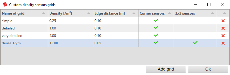
Density sensors grids - these grids use an advanced algorithm
that places the sensors on the surface in a density grid, along the
edges and finally in the corners (segment ends). This type of grid is
particularly suitable for surfaces with complex shapes, the mode
"Sensors coverage area" is recommended (see below advanced settings
preferences).
The algorithm has 4 parameters:
-
Density: number of sensors per square meter. This density is
indicative, the final density may be slightly higher.
-
Distance to the edges: minimum distance between sensors and edges of
surfaces.
-
Corner sensors: try to put sensors in the corners of the surface.
-
3x3 sensors: try to have at least 3 sensors in each direction,
possibly at the cost of increasing the density.
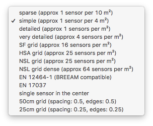
The provided grids:
-
Sparse - approximately 1 sensor every 10 square meters,
distance to the edges: 10cm, corner sensors: yes, 3x3 sensors: no.
-
Simple - approximately 1 sensor every 4 square meters (sensors
2 meters apart in each direction), distance to the edges: 10cm, corner
sensors: yes, 3x3 sensors: no.
-
Detailed - approximately 1 sensor per square meter, distance to
the edges: 10cm, corner sensors: yes, 3x3 sensors: no.
-
Very detailed - approximately 4 sensors per square meter (a
distance of about 50cm between sensors), distance to the edges: 10cm,
corner sensors: yes, 3x3 sensors: no.
-
SF, HSA, NSL grids: these are very dense grids intended for certain
calculations such as the calculation of horizontal sight angle.
-
EN 12464-1 standard - grid in accordance with
EN 12464-1 standard
requirements, with approximate distance between sensors p = 0,2 ×
5^log10(d) meters, where d is the longest dimension of the calculation
area if the length-to-width ratio is between 0.5 and 2.0. For other
ratios shorter dimension is used for d.
Nota:
- this grid is used for BREEAM calculations mode,
- for a length d=10m, the size of the mesh is 1.00m.
-
EN 17037 standard - grid in accordance with
EN 17037 standard
requirements, with approximate distance between sensors p = 0,5 ×
5^log10(d) meters, where d is the longest dimension of the calculation
area if the length-to-width ratio is between 0.5 and 2.0. For other
ratios shorter dimension is used for d. The surface of the mesh excludes
a band of 0.50m along the walls, the grid is calculated on this reduced
surface.
Nota:
-
grid used by default for Daylight Factor and Horizontal Sight Angle
in EN 17037 mode,
- for a length d=10m, the size of the mesh is 2.50m
-
the density of the mesh proposed by EN 17037 standard is much lower
than for EN 12464-1 (in ratio greater than 6).
-
Single sensor in the center - the surface receives only one
sensor, located in the center (or close to the center for surfaces with
holes).
Note: grid used by default for APSH calculation.
-
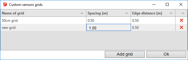
Classic sensors grids - regular rectangular grid (the spacing
between sensors is fixed), this is the simplest grid.
These grids have 2 parameters:
-
Spacing: distance between the sensors. The distance is the same in
both directions.
-
Distance to the edges: minimum distance between sensors and edges of
surfaces.
Provided grid:
-
50cm grid - grid with a sensor every 50cm and a minimum
distance to edges of 50cm.
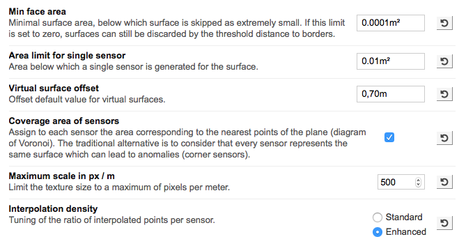
Advanced preferences settings
The following parameters are adjustable in the advanced preferences of
each extension and affect the interpretation of the sensors:
-
Min face area - Minimal surface area, below which surface is
skipped as extremely small. If this limit is zero, a surface can still
be discarded if the distance limit at the edges of the sensor grid
does not allow a sensor to be positioned.
-
Area limit for single sensor - Area below which a single sensor
is generated for the surface.
-
Coverage area of sensors - Boolean - If enabled, assign to each
sensor a coefficient corresponding to the area covered by the nearest
points (Voronoi diagram). The traditional alternative is to consider
that each sensor represents the same surface, which can lead to
anomalies (sensors in the corners). In general this option is
recommended to obtain coherent and precise results, but it is not
recommended for the calculations having to respect a standard
specifying that each sensor must have the same "weight" (for example
BREEAM).
These 2 options have no influence on the sensors and the values
returned in the reports, they only concern the rendering of the
textures:
-
Interpolation density - Adjusting the ratio of interpolated
points by sensor, improve the graphic rendering (for modes RBF and
linear interpolation).
-
Maximum scale in pixels / meter - Limit the texture dimension
to a maximum of pixels per meter. The largest dimension of a texture
is defined in the preferences (for example 1024 pixels). This second
parameter also makes it possible to enforce a limit based on the
dimensions of the surfaces. This makes it possible to maintain a
coherent graphic rendering for successive calculations on surfaces of
very different sizes.
Custom sensors grids
Two dialogs allow you to define custom sensors grids for both types
(density and conventional). These dialogs take the parameters described
above. The default grids are presented in these dialogs for information
purposes.
Features
-
Local storage - defined grids are saved in the local instance
of SketchUp and can be used on any model (either as the main sensors
grid or for exception surfaces).
-
Model storage - any grid used in a model is also stored in the
SketchUp model.
-
Removing grids - Removing a grid (red cross icon) deletes the
grid only locally, but never from the model that uses it. As a result,
there is no point attempting to erase a grid used in the current
model. To remove a grid from a model, it must be ensured that it is no
longer used by any calculation on the model.
-
Automatic loading vs naming - When loading a model, the grids
used by the model are automatically loaded. The name of the sensors
grids is therefore indicative, 2 identical grids can exist under 2
different names, 2 grids with the same name but with different
parameters can coexist. The management of naming rules is left to the
local organization.
Density sensors grids
The dialog is accessible from the SketchUp menu:
Extensions -> De Luminae -> Global Parameters -> Custom
Density Sensors Grids
It is also accessible from the Grid Exceptions dialog on surfaces.
Classic sensors grids
The dialog is accessible from the SketchUp menu:
Extensions -> De Luminae -> Global Parameters -> Custom
Sensors Grids
It is also accessible from the Grid Exceptions dialog on surfaces.
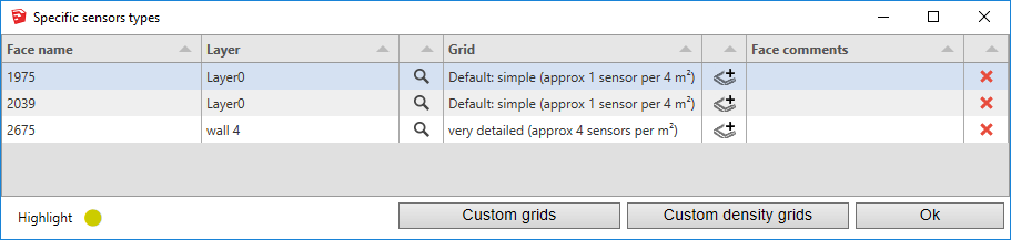
Exceptions - sensors grid specific to a surface
This dialog allows you to select a specific sensors grid for a model
surface. It is accessible through the Exceptions button to the right of
the main grid selector.
Each line of the table corresponds to a surface of the model.
-
Windows only : click on "loupe" icon displays a mask on the
model that locates the surface.
-
Mac OS only : selecting a row in the table displays a mask on
the model that locates the surface.
-
Clicking on a face of the model loads the face into the table (or
selects it). Initially, the table is empty if all the surfaces use the
default grid, it is then necessary to click on the faces to be
modified.
-
The Custom grids and Custom density grids buttons
provide direct access to grid characteristics via the dialogs
described above.
Definition of columns:
-
Face name - Name of the face (by default its numerical
identifier). The name is editable.
-
Layer - Name of the layer to which the surface is attached.
-
Grid - The name of the currently assigned grid. If the default
grid is used, the name of the grid is preceded by the word "Default:".
Click on the cell to select a grid to use from the drop-down list
(browse through the list using the mouse wheel or keyboard).
-
Add layer icon
 - Apply the grid of this surface to all surfaces listed in the table
that are attached to the same layer.
- Apply the grid of this surface to all surfaces listed in the table
that are attached to the same layer.
-
Face comments - Comment associated with the face. The comment
is editable.
-
Delete icon - Remove the face of the table, so the face uses
the default grid.