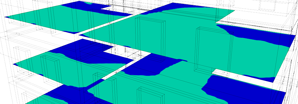
The Sky Factor is the ratio of the illuminance received directly through openings (unglazed), to the illuminance on a horizontal plane due to an unobstructed hemisphere under a sky of uniform luminance distribution. The Sky Factor does not include reflected light from outdoor or indoor surfaces.

The Sky Factor indicator is mostly used in UK policies, both for new constructions assesment and to work out whether a proposed new building will affect the 'Rights of Light' of an existing building. The impact of the new building on the 0.2% limit position allows to evaluate the loss of light.
This implementation of the Sky Factor indicator uses a ray-tracing simulation of direct illumination without interior or exterior reflexions. This extension does not use the Waldram diagram method.
Consequently, this extension does not claim to replace the method of Waldram if use of that method is required.
Sky Factor
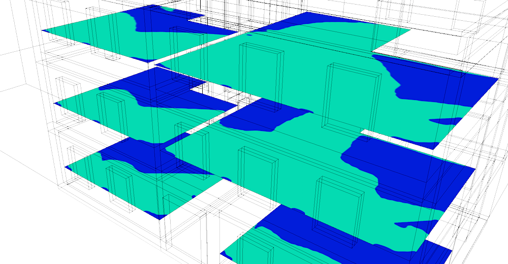
The most common use is to determine the portion of an area with an indicator value greater than 0.2%. The measurement is carried out on a virtual plane located 0.85m above the floor.
The distance of 0.85m is the default setting of the virtual surfaces for this extension (value configurable in the preferences). For the use of virtual surfaces, see page: Create virtual surfaces.
The traditional method of evaluating the 0.2% delimited area uses "Waldram diagrams". This extension uses a different method to determine the areas passing the criterion: the computation is made on a significant number of sensors, then the area is computed by assigning to each sensor the portion of surface it covers (coverage of Voronoï polygons).
See below under How to use Sky Factor Extension.
Rights of Light
In a 'Rights of Light' context, the objective is to establish a comparison between 2 situations: before and after a new construction. The extension integrates a functionality of comparison between 2 calculations carried out beforehand and provides the gains and losses of lighting, in the form of a table and false colors textures on the SketchUp model.
See below under How to use Sky Factor to make a "Rights of Light" comparison.
Important: layers corresponding to glazing must be hidden. You can set the glazing layers invisible within SketchUp, or use the DL-Light transparency feature (see page Make layers "transparent").
Open SketchUp model. Follow recommendations to prepare your model for DL-Light calculations.
Open Sky Factor dialog from toolbar
![]() or menu
Extensions -> De Luminae -> Sky Factor -> Activate
extension
and enter the parameters of the calculation.
or menu
Extensions -> De Luminae -> Sky Factor -> Activate
extension
and enter the parameters of the calculation.
Fields description:
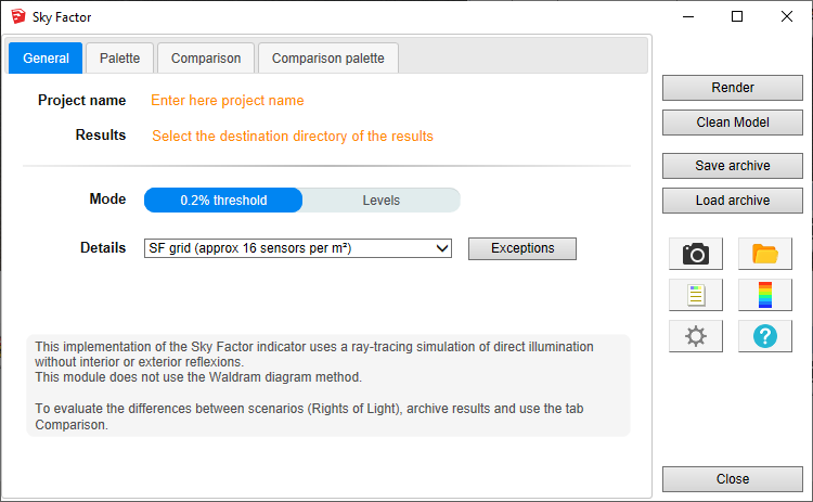
Project name - Project name is used during export and for output filenames generation. The SketchUp model name is used by default.
Results - Directory where model
will be exported for calculation. It should be an existing or a
new directory where user has appropriate write/read privileges.
When calculation is started model geometry and resulting files
will be saved in skyfactor_output
subdirectory.
For SketchUp projects stored on network disk (Windows), see
Work on a copy of the model.
Mode - Calculation mode
selection:
Both modes uses the same computation, but the graphical
representation differs:
Details - By default, the calculation uses a dedicated grid 'SF grid' with 16 sensors per square meter. Any other grid can be used, however Sky Factor calculation requires a dense grid to achieve sufficient precision.
DL-Light allows to choose:
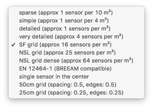
See sensors selection for more information on the choices of proposed sensors.
The '0.2% threshold' mode uses a bicolor palette. On this palette only the threshold and colors can be modified. The 'Levels' mode uses a palette whose all parameters can be modified.
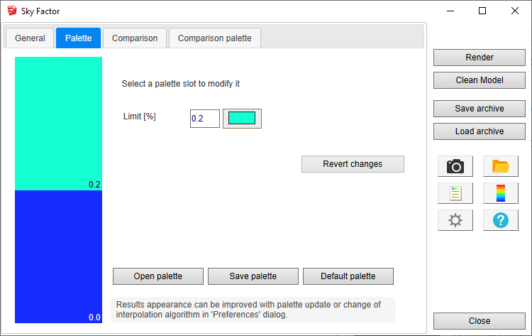
After entering the parameters, select surfaces and press
Render
or
 button.
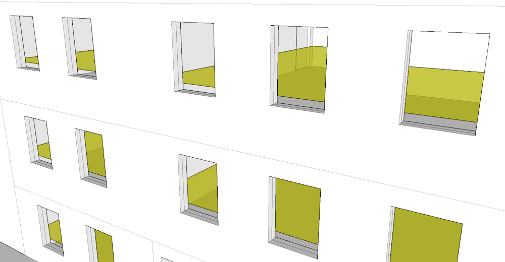
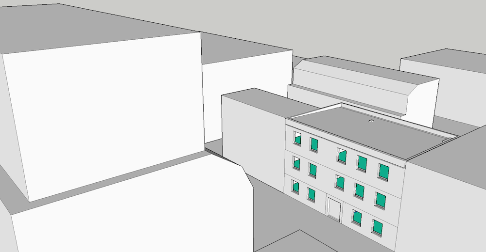
The model shown contains openings on 3 sides and complex obstructions. Notice at the top left a block marked as transparent (see page Make layers "transparent"):
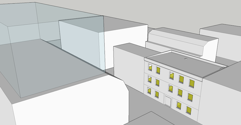
Calculation time depends on number of selected surfaces and model complexity.
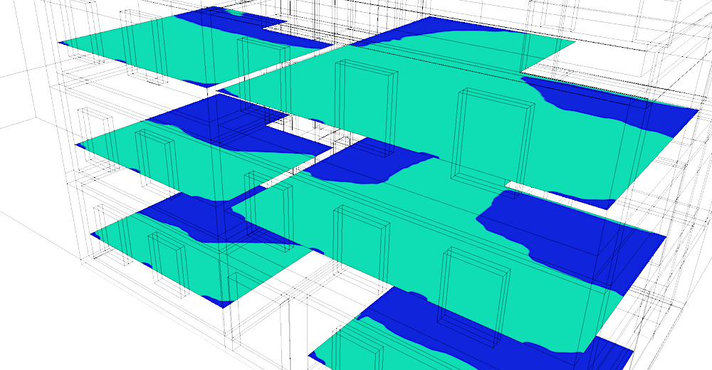
When results are imported, selected surface will have appropriate false colors and Palette and Report dialogs will be opened.
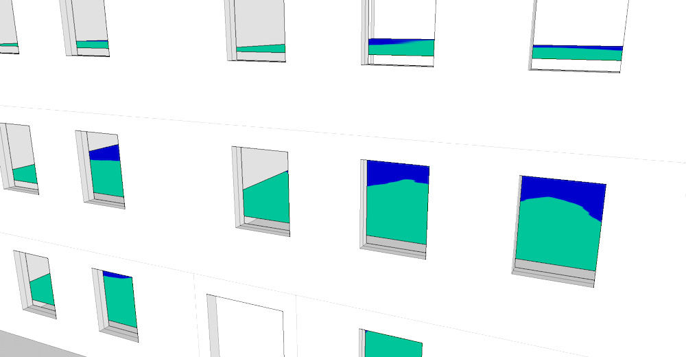
Use the
![]() icon to display only false color textures:
icon to display only false color textures:
Results analysis.
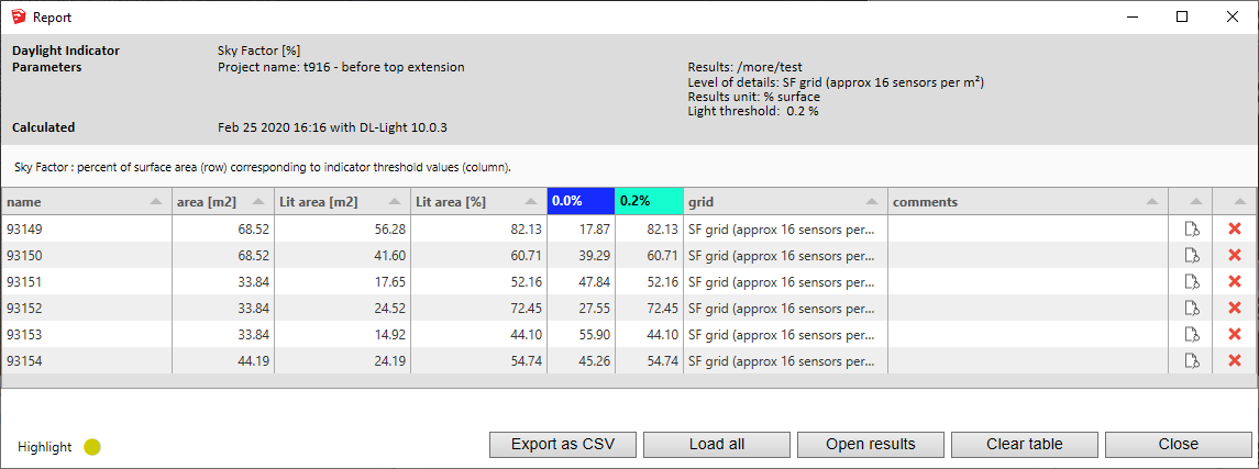
The Report dialog
 displays the distribution of results over current palette and
calculation input parameters.
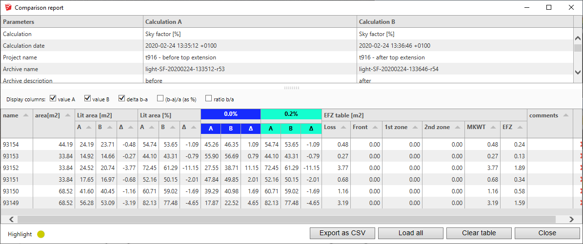
The '0.2%' threshold defines the 'lighting' limit of the surface. For each surface, the total area of the surface (m²) and the lit area (both m² and percentage) are displayed.
For further calculations in the same model:
 .
.
DL-Light uses a calculation cache algorithm. It automatically detects if a surface requires recalculation or if a previous result can be reused. By default, the cache keeps the information of the last 10 calculations (value configurable in the preferences).
Archiving results:
DL-Light allows to archive all the results of a calculation: reports, textures and calculation steps (exported Radiance model ...). This archive can be reloaded on the model, subject to using exactly the same model as during the calculation.
See the page Archiving results for more informations about this feature.
See the page Comparison of results for more informations about comparison of archives.
Snapshots:
Current SketchUp model view with imported results can be exported with
palette
 or without palette
 to png format. Open the folder of images with
 .
.
This option is not supported in trial version of the extension (see
licence information).
In a few words: calculate and archive 2 versions of the model, then use the "comparison" tab.
Calculate the Sky Factor indicator for the model as described in the previous section.
Archive the result, see page Archiving results.
Display a difference on the SketchUp model to evaluate in terms of
"Rights of light".
For an efficient organization, it is recommended to place the geometry
changes (new constructions) in layers, to hide them for the first
simulation, then to make them visible for the second.
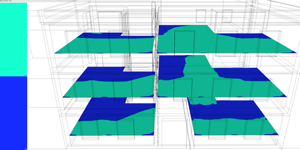
In this example, the layer transparent in the previous calculation has been restored:
Calculate and archive the Sky Factor indicator for the same surfaces, with the same "0.2%" palette and the same graphic parameters (type of interpolation, texture resolution).
Open the "Comparison" tab, it allows you to select two archives A and B to compare. The comparison module will calculate the ratios for the difference "B - A".
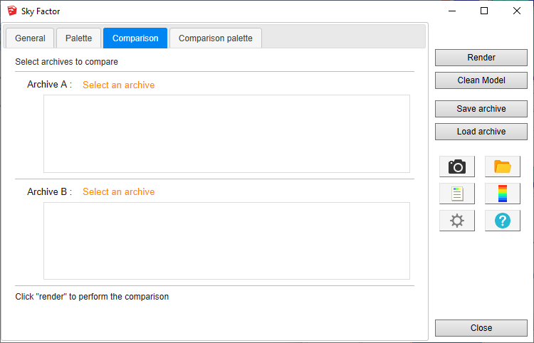
Select the archives of previous computation.
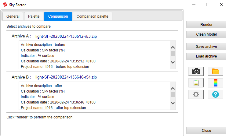
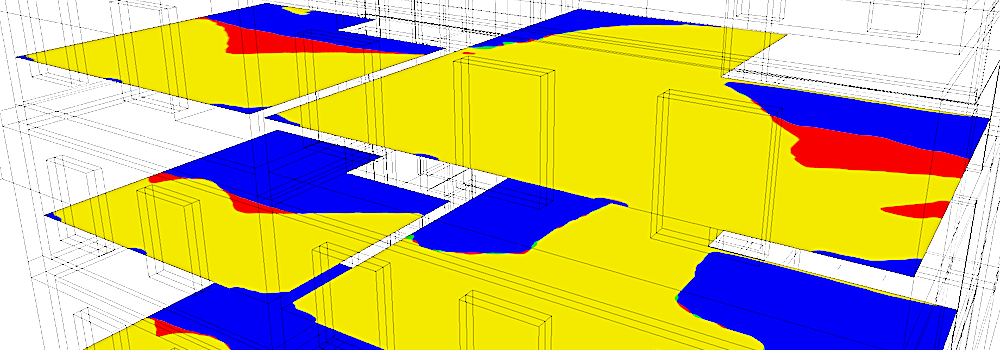
Press Render, the result of comparison should be displayed quickly. Areas with loss of illumination are shown in red.
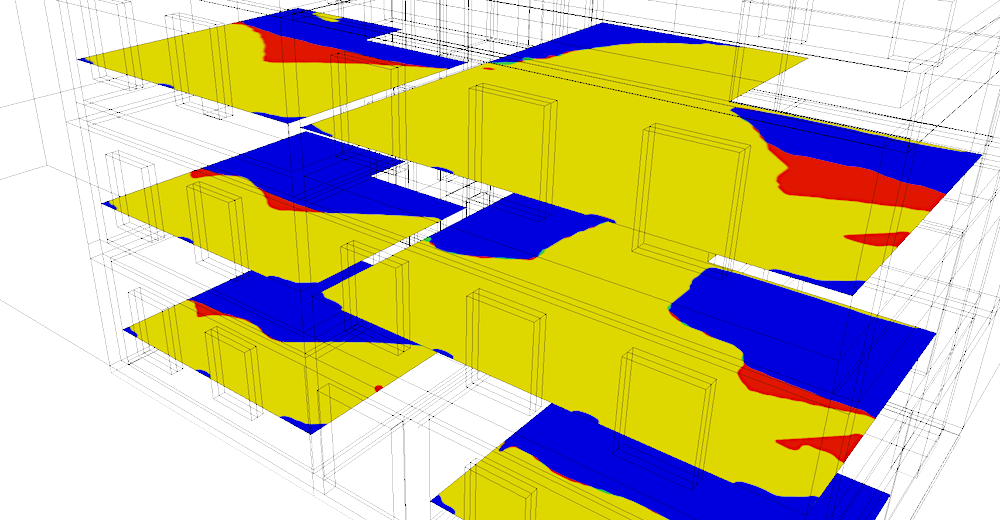
The red zone corresponds to the difference between the results "before" and "after":

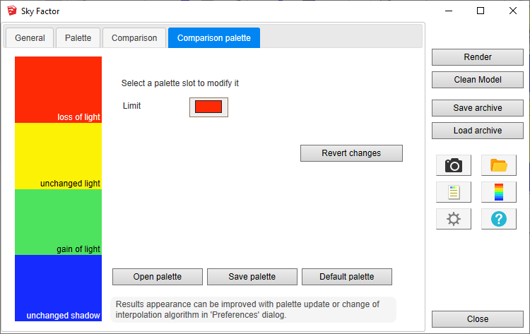
To change the colors, just edit the comparison palette in the last tab and press Render again.
The report shows distribution of results and ratios for before / after comparison. On the right side of the report are specific columns for "Rights of light" analysis called "EFZ" (Equivalent First Zone). Display of EFZ columns is an option in the preferences.
